Concrete foundations provide the strength that buildings need, but conventional construction methods often use more material than structural performance requires. As the construction industry works to reduce costs, waste, and carbon emissions, 3D printing is making it possible to rethink how foundation components are designed and produced.
Recent projects and design studies indicate that optimized 3D printed foundation systems can cut concrete use by as much as 56 percent compared with conventional solid alternatives. This reduction is not automatic or universal. It depends on factors such as structural loads, soil conditions, printing technology, material formulation, and engineering approval.
Why Conventional Foundations Consume So Much Concrete
Traditional foundations are commonly built with reinforced concrete poured into temporary formwork. To simplify design and installation, footings, foundation walls, and slabs often rely on uniform dimensions and solid cross sections. These familiar geometries are practical, but they may place concrete in areas where it contributes little to the component’s structural performance.
Conservative design allowances can add further material. Engineers must account for uncertain soil behavior, construction tolerances, water exposure, load variations, and local code requirements. Standardized formwork also limits the range of economical shapes, making a thicker rectangular element easier to construct than a lighter component with curves, cavities, or changing wall thicknesses.
The environmental cost of excess material
Concrete production has impacts beyond the volume placed on a jobsite. Cement manufacturing is energy intensive and releases carbon dioxide through both fuel consumption and the chemical conversion of limestone. Aggregates must also be extracted, processed, and transported, while concrete mixing and delivery require additional energy and water.
Reducing concrete volume can therefore lower embodied carbon, transportation demand, and material costs. The greatest benefit comes when the reduction is achieved without compromising load capacity, durability, fire resistance, or service life. For foundations, this requires careful coordination among architects, structural engineers, geotechnical engineers, material specialists, and construction teams.
How 3D Printing Removes Concrete Without Sacrificing Strength
Construction 3D printing builds components layer by layer according to a digital model. Unlike conventional casting, the process does not always require disposable or custom formwork. This freedom allows designers to create hollow sections, internal ribs, curved walls, and variable thicknesses that would be difficult or expensive to produce using standard molds.
The reported concrete reduction of up to 56 percent generally comes from geometry optimization rather than from replacing concrete with a weaker material. Digital analysis identifies the paths through which forces travel from the building into the ground. Material can then be concentrated along those load paths and reduced in areas carrying less stress.
Topology optimization and load based design
Topology optimization uses computational methods to determine where material is structurally necessary within a defined space. For a foundation component, the design process can consider vertical loads, bending, shear, settlement, wind forces, and other project specific demands. The resulting geometry may resemble a network of ribs or branching supports rather than a conventional solid block.
Before printing begins, engineers refine this geometry to account for constructability. Features must be compatible with nozzle dimensions, layer height, print speed, reinforcement placement, and the behavior of fresh concrete. Openings and cavities also need to avoid trapping water or creating inaccessible areas that could undermine long term durability.
Material efficiency depends on the complete system
A printed shape may use substantially less concrete, but its performance depends on more than geometry. The printing mixture must flow through the equipment, hold its shape after deposition, bond reliably between layers, and develop the specified strength. These requirements can lead to mixtures with different cement, aggregate, and admixture proportions than conventional concrete.
For this reason, concrete volume and environmental impact should be evaluated separately. A 56 percent reduction in volume can represent a major efficiency gain, but the actual carbon savings depend on the mixture design, reinforcement strategy, energy source, transportation distance, and amount of rejected material. A credible comparison uses equivalent structural performance and measures the full foundation system rather than focusing only on the printed portion.
Where 3D Printed Foundation Systems Can Be Used
Not every foundation is suitable for additive construction. The strongest applications are typically projects where geometric optimization, repeatability, or reduced formwork can offset the cost of digital design and specialized printing equipment. Potential uses include isolated footings, strip footings, grade beams, foundation walls, pile caps, and permanent formwork that is later filled with conventional concrete.
Printed permanent formwork
One practical approach is to print a hollow shell that remains in place during and after construction. Reinforcement can be installed inside the shell before the cavity is filled with concrete or grout. This method combines the geometric freedom of printing with familiar reinforced concrete design principles.
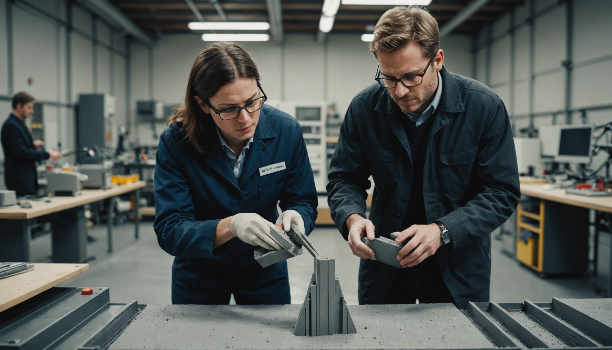
Permanent printed formwork can create curved surfaces, integrated ribs, service openings, and variable wall thicknesses without requiring custom timber or steel molds. However, the shell, infill, and reinforcement must act together as intended. Engineers must verify bond behavior, dimensional tolerances, moisture exposure, and whether the printed material is structural or serves only as formwork.
Factory printed foundation components
Foundation elements can also be printed in a controlled factory and transported to the site. Offsite production provides greater control over temperature, humidity, material batching, machine calibration, and curing. It may also allow components to be inspected before installation.
Transportation and lifting impose limits on component size and weight. Connection details become especially important because individual printed pieces must transfer forces safely after assembly. Designers may divide a large foundation into modules, but the joints cannot become weak points for shear transfer, water penetration, or long term movement.
Onsite printing
Onsite printing can reduce transportation and allow larger continuous elements to be produced. A mobile gantry or robotic arm deposits material directly where the foundation is needed.
Jobsite conditions are less predictable than factory conditions. Wind, rain, temperature, dust, ground movement, and interruptions in material supply can affect layer quality. The printing platform must remain level and stable, while the digital model must correspond accurately with survey data and excavation conditions.
Reinforcement Remains a Central Engineering Challenge
Concrete performs well in compression but has limited tensile capacity. Conventional foundations therefore use steel reinforcement to resist bending, control cracking, transfer loads, and connect walls or columns to footings.
Reinforcement can be introduced by pausing the print to place bars, printing around prefabricated cages, inserting vertical bars into cavities, or filling printed shells around conventional reinforcement.
Designing around reinforcement placement
Highly optimized cavities may look efficient in a digital model but leave insufficient room for workers to position bars or for concrete to flow around them.
Interfaces between printed layers also require attention. Depending on the material and time between passes, layer boundaries may respond differently to tension, shear, moisture, and freeze thaw exposure than monolithic cast concrete.
Soil Conditions Still Govern Foundation Performance
A lighter foundation can reduce the pressure applied to the ground, but it cannot compensate for inadequate geotechnical investigation. Soil bearing capacity, settlement, groundwater, frost depth, expansive soils, erosion, and seismic conditions continue to determine the appropriate foundation type and depth.
Optimized geometries may distribute pressure differently from solid rectangular footings. Engineers must confirm that the contact area is sufficient and that soil stresses remain within acceptable limits.
Preparing a reliable printing surface
Onsite printing requires accurate excavation and a stable base. The subgrade may need compaction, granular leveling material, drainage, or a lean concrete working surface. If the first printed layers are not level and properly supported, dimensional errors can accumulate as the component rises.
Drainage details must also be incorporated into the design. Internal voids should not collect groundwater, and channels should not create routes for water to reach reinforcement.
How a 56 Percent Reduction Should Be Interpreted
The figure of up to 56 percent describes a high level result under particular design and comparison conditions. It should not be treated as a guaranteed saving for every printed foundation.
The baseline also matters. Comparing an optimized printed component with an oversized solid reference can produce a large percentage reduction. Comparing it with an already efficient conventional design may produce a smaller difference.
Volume savings versus total project savings
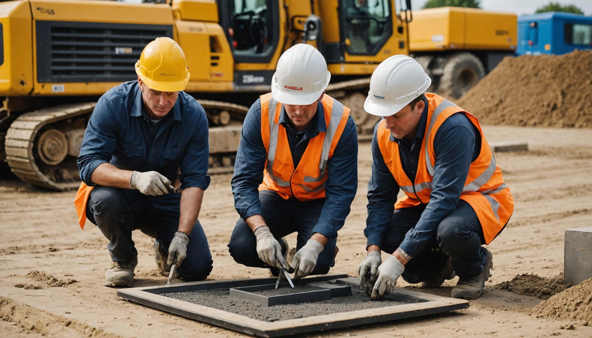
Using less concrete does not always mean the complete foundation will cost less. Savings from concrete and formwork may be partly offset by engineering, testing, equipment mobilization, printing mixtures, reinforcement installation, quality control, and operator training.
Schedule benefits are also project specific. Printing can reduce the time needed to fabricate and strip formwork, but reinforcement placement, curing, excavation, inspection, and utility coordination still take time.
Quality Control From Digital Model to Finished Foundation
Successful construction depends on maintaining continuity between engineering intent and field production. The digital model must include approved dimensions, openings, reinforcement zones, tolerances, and print paths.
Monitoring the material and print process
Fresh material should be checked for consistency, pumpability, buildability, temperature, and open time. The mixture must be fluid enough to move through the system but stiff enough to support subsequent layers.
During printing, operators can monitor bead width, layer height, deposition rate, nozzle position, and elapsed time between layers. Cameras, scanners, and sensors can compare the printed geometry with the digital model.
Testing hardened performance
Compressive strength remains important, but it is not the only relevant property. Testing may also cover flexural strength, tensile behavior, interlayer bond, shrinkage, permeability, reinforcement bond, abrasion resistance, and durability under the expected exposure conditions.
Samples should reflect the actual printing direction, equipment, layer interval, and curing method. Conventionally cast test cylinders may not capture weaknesses associated with the layered process.
Design Codes, Approval, and Risk Management
Building codes were generally written around established cast concrete and masonry methods. Printed foundation systems may not fit neatly within prescriptive provisions, particularly when they use novel materials, thin shells, complex internal cavities, or unconventional reinforcement.
Approval may therefore rely on performance based engineering, project specific testing, third party evaluation, and close coordination with the authority having jurisdiction. Documentation should define material properties, design assumptions, manufacturing controls, inspection procedures, and acceptance criteria.
Creating a clear responsibility structure
Digital construction involves several parties, including the engineer, printer manufacturer, material supplier, software provider, equipment operator, contractor, and inspection team. Contracts should identify who is responsible for model accuracy, print path generation, material consistency, reinforcement placement, machine calibration, and final acceptance.
A traceable production record can document mixture batches, weather conditions, print times, interruptions, inspection results, and test specimens. This information supports quality assurance, future maintenance, and investigation if performance issues arise.
What Is Needed for Wider Adoption
Broader use will depend on standardized testing, code recognition, reliable reinforcement methods, and evidence from completed projects. Printers must also become easier to mobilize and integrate with excavation, surveying, concrete supply, and inspection workflows.
The most credible projects will treat 3D printing as part of an engineered foundation system rather than as a stand-alone machine process. When digital optimization, geotechnical design, durable materials, reinforcement, and quality control are coordinated, substantial concrete reductions may be achieved without compromising safety or service life.